Multilayer PCB Design, IC package design, PCB library development
Argus Systems is a globally recognized PCB Electronics Hardware Design Company in India, USA, UK, Germany, France, UAE, Saudi Arabia, and Australia Offering Product Engineering services worldwide with strong presence in Consumer, Industrial, Telecom, Defense and Aerospace domains. We provide turnkey Electronic product design services from concept definition to development of a fully tested and standard compliant product ready for volume manufacturing. We innovate, research and help in creatively designing new products as per requirement.
Argus has established Electronic Design standards for acceptance and delivery which results in faster turnaround time with least error. We are customer centric and deliver high-quality multilayer, high speed PCB design and manufacturing, taking into consideration of real-world Electronic Manufacturing and test requirements. Our Electronic Hardware design services includes Embedded hardware design, High Speed PCB design, Low current High Voltage PCB Design, Low Voltage PCB Design, High current PCB design, Digital PCB Design, Analog PCB Design, RF PCB Design, Mixed Signal PCB Design.
The complexity of development of products starts from idea to designing , prototyping, manufacturing and finally going into production. The product development cycle requires expertise in all fields and in-depth knowledge of many technologies. Smaller start-ups and product companies who do not possess in depth knowledge of the product design and development turns to other companies for their requirements. This helps the start-ups to focus on their strengths and utilize other companies strength to reduce the time to market and build a better product.
Product development broadly can be divided into mutiple stages.Each of these phase requires expensive tools and capital equipment expenditures which can be lowered significantly if these can be outsourced to the external custom electronic design , embedded hardware design team that has the required tools and experience. This will in turn reduce the operational cost of the start-up business and help them to focus on their strategy and lean them to profitability.

PCB design services
- Outsourcing Your Printed Circuit Board Design ( Multilayer High speed PCB design, Analog PCB design, Mixed Signal PCB design, RF PCB design, High voltage low current PCB design, Low voltage PCB design, high current PCB design) encourages accountability as Argus experienced and reputed EMS team will be working on the project which in turn minimizes the chances of failure.
- The high costs of PCB CAD Design tools, maintenance and staff training also make a good case for this approach. However, handing over your latest concept to a design bureau is not a decision to be taken lightly. The design bureau should be capable with proven experience in delivering the product or design.
- Outsourcing electronic design, embedded hardware design has many direct benefits some of which are less time to market, less operational cost, more time for focusing on actual product idea and last but not least delivering quality product.
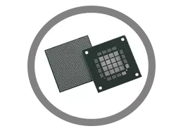
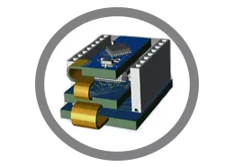
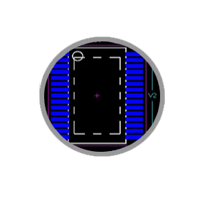
IC Package design
- We offer IC package design services for emerging design technologies like Flip Chip, stacked die, POP, PIP in addition to wire bond technology for mixed signal and RF-IC products.
- As high speed communications data rate is going up, IC packaging become a critical design parameter. The interconnect (substrate) design of IC Packages needs high care and expertise, as the signal and power integrity of the substrate is crucial due to high frequency signals and low power of operation.
- Our IC Package design has capability to perform parasitic analysis, Simultaneous switching noise and IBIS modeling and mechanical simulations.
- Wire bond, Flip chip, Stacked die, CSP, POP, PIP
- IC package Signal Integrity Analysis
- IC package Power Integrity Analysis
- IC package Electrical Modelling
PCB library development
- Dedicated team for customer-specific PCB Library development or Standards compliant PCB CAD Library development and management which include schematics symbols, PCB footprint, and 3D models
- Schematic Symbol creation according to ANSI, IEC or customer Specific standard across various EDA tools
- Component footprint creation according to IPC-2221 and IPC7351 or customer Specification across various EDA tools
- Quality Control and Process-driven development ensures zero defect PCB library components
- Expertise in creating complex component PCB libraries, press-fit components and electromechanical components
- Customized PCB library development and maintenance for each customer.
- We have a huge collection of PCB components in global library from the leading EDA tools and a dedicated library team to quickly turnaround the symbols and footprint requests.

RF PCB Design Challenges
- Microwave and RF pcb design and are highly sensitive to noise.
- Matching Impedance is challenging as higher the frequency the lower the tolerance.
- RF design Expects Zero Return loss.
- Cross talk is directly proportional to the edge rates of the active line.
- Dissipation factor and dielectric constant value can cause huge losses.
- Taking account of Skin Depth loss: At higher frequencies electrons flow on the outer surfaces of the conductor knows as skin effect and causes the effective resistance of the conductor to increase.
- Any one of the above issue is sufficient to cause failure in the product and should be handled properly in the design phase itself.
- These issues often creep in with slight modification of placement and layout of components, vias and planes if not planned properly in advance or even while incorporating the feedbacks.
-
RF PCB layout design
- At Argus we believe each invention and resulting product is unique , so the method of RF and Microwave PCB design should be done after analyzing the requirements thoroughly.
- Use a multilayer PCB, if possible.
- Make sure return current paths are not routed under any of the sensitive Microwave and RF pcb Design circuit blocks.
- As far as possible have common low-impedance ground plane.
- Use of a solid ground plane is recommended as it minimizes inductance but at the same time if not used wisely can cause capacitance problems to sensitive nodes of the circuit.
- Place RF signal lines at distances to avoid cross-talk.
- The length of the via including their inductance and capacitance value have a greater affect on very high frequency so its use with signal traces should be minimized and if possible can be avoided.
- Short winding traces should follow “two points-straight line-shortest distance” method while reducing the current loop area where the receiver part is placed as close as possible to the input. This helps in reducing delay time as well as noise on the path of the PCB and improved EMI.
- Differential Traces should be placed and routed together around obstacles and should be of the same length to keep equal delays.
- Use multiple ground vias around the signal via to maintain the characteristic impedance.
- Try to have multiple vias for both power supply and Ground connection.
- Avoid guard rings for low leakage systems.
RF PCB design
- RF and Microwave PCB design is considered to be a niche domain requiring exceptional understanding of constrained, exhaustive guidelines and general pitfalls.
- Selection and placement of components even PCB material if not chosen wisely could cause complete failure of the RF and Microwave PCB design, which could have been done with utmost care at the design phase.
- It is highly recommended to give your RF and Microwave PCB design projects to only specialized firm.
- The team which in highly experienced in RF and Microwave PCB design and follows standard processes can only suggest and overcome the challenges faced by RF and Microwave circuits.
- RF (Radio Frequency) is a part of electromagnetic spectrum having frequencies from 3 kHz to 300GHz with wavelengths ranging from 1 mm to 100 KM, travelling at the speed of light.
- A part of Radio frequency spectrum between 300MHz to 300GHz is known as Microwave which includes UHF, EHF and SHF band.
- RF signals can be characterized as high frequency analogue signals.
- As the signals are analogue in nature and mostly travel over-the-air the amplitude, voltage and current levels are not defined but vary as per environment and medium.
- To add to the complexity of the analogue signal, its not single frequency but generally band of frequencies so the RF and Microwave PCB design and circuits are designed to pass the desired band and filter out the rest.